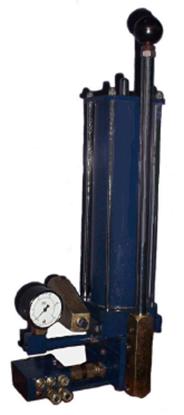
CENTRALIZED HAND OPERATED TWO
LINE GREASE LUBRICATION SYSTEM
I. Schematic
Diagramme:
II. Principle of Operation:
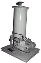
Grease is supplied by
the Two Line Hand Pump through the Grease Filters and the Two Line
Distributors, as shown in the schematic diagramme. With the Reversing Valve of
the Hand Pump at one of the two positions, discharge of grease takes place from
one of the two primary pipelines (from Pump to Distributor ) when the Pump is
operated. If the primary pipeline is already completely pre-filled, the
Distributors will operate one after another with the continued operation of the
Pump. The operation of the Distributors will take place in any one mode i.e.
the stem at the indicator portion will either move from the in position to
the out position or vice versa. If the secondary pipeline ( from Distributor
outlet to lubrication point ) is already pre-filled, grease will go to the
corresponding lubrication point. Once all the Distributors have completely
operated, further discharge will not be possible. At this condition, the handle
of the Hand Pump will become hard to operate and the Pressure Gauge provided
with the Pump will show increase in pressure without any appreciable movement
of the handle. This signals the completion of the first half of the lubrication
cycle. It is to be noted that small internal discharge that takes place inside
the Distributors is brought back to the Reservoir of Hand Pump through the
primary pipeline other than the one working as the discharge line. The
Reversing Valve of the Hand Pump is now to be shifted to the other position.
When the Pump is operated, the Distributors will once again operate in the
opposite mode and the discharge will take place through the other set of
outlets. Once all the Distributors have operated fully, the second half of the
lubrication cycle is completed. It may be noted that, if single outlet type
Distributors are used instead of double outlet type as shown in the above
schematic diagramme, the discharge will take place from the single outlet in
both positions of the Reversing Valve.
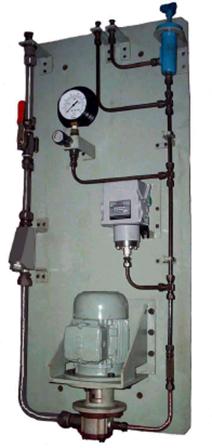
CENTRALIZED AUTOMATIC TWO LINE GREASE LUBRICATION SYSTEM (with Hydraulic Reversing Valve)
I.Schematic Diagramme:
II. Principle of Operation :
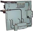
Grease
is supplied by the Two Line Motorized Pumping Station through the Hydraulic
Reversing Valve (the type shown being pilot reversing type), Grease Filters and
the Two Line Distributors, as shown in the schematic diagramme. In the initial
condition, the stem of the Reversing Valve is at the ‘out’ position, with the
Limit Switch in the actuated condition. When the Lubrication System is made
‘ON’ by starting the Motor of the Motorized Pumping Station, discharge of
grease takes place from one of the two primary pipelines; the maximum pressure
in the line is limited by setting in the Main Relief Valve. After the operation
of the Distributors, grease will flow through the single outlet line of the
Shuttle Valve after overcoming the pressure set in the Changeover Relief Valve
and will reverse the position of the Reversing Valve. The stem of the Reversing
Valve will move to ‘In’ position, which means the completion of the first half
of the lubrication cycle. Grease flow will now start in the other primary line
and once again, after the oper-
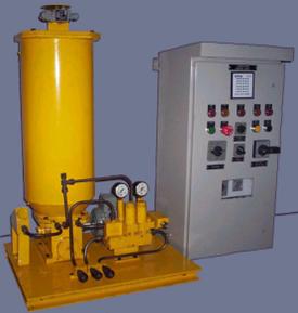
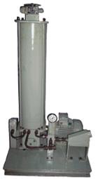
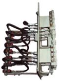
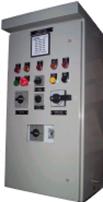
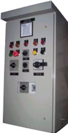
Two Line Motorized Pumping
Station with Electrical Control Panel
ation of the Distributors, there will be reversal
in the position of the Reversing Valve. The stem of the Reversing Valve will
move to the ‘Out’ position and in the process will operate the Limit Switch
which will give command for stopping the Electric Motor operating the Pump.
This signals the completion of the second half of the lubrication cycle. The
next lubrication cycle is started automatically after pre-set time of the Timer
provided in the Electrical Control Panel.
CENTRALIZED AUTOMATIC TWO LINE GREASE LUBRICATION SYSTEM (with ELECTROMAGNETIC REVERSING VALVE)
I. Schematic Diagramme:
II. Principle of Operation :
Grease
is supplied by the Motorized Pumping Station through the Electromagnetic
Reversing Valve, Grease Filters, Metering Feeders, End Pressure Relay, as shown
in the schematic diagramme. In the initial condition, one of the two Limit
Switches fitted with the End Pressure Relay is in the actuated condition. When
the Lubrication System is made ON by starting the Motor of the Motorized
Pumping Station and energizing one of the two Solenoids of the Electromagnetic
Reversing Valve, discharge of grease takes place from one of the two primary
pipelines; the maximum pressure in the line is limited by setting in the Main
Relief Valve. After the operation of the Metering Feeders, grease will flow
through the 2-position Valve of the End Pressure Relay after overcoming the
pressure set in the corresponding Changeover Relief Valve and will reverse the
position of the 2-position valve. The stem of the 2-position Valve will operate
the other Limit Switch, which means the completion of one lubrication cycle and
the Motor will be stopped and the Solenoid of the Electromagnetic Reversing
Valve will be de-energized. At suitable time interval set by Timer, Motor will
be started again automatically and the other Solenoid will be enrgized. Grease
flow will now start in the other primary line and once again, after the
operation of the Metering Feeders, there will be reversal in the 2-position
Valve of the End Pressure Relay. The other stem of the End Pressure Relay will
move to the Out position and in the process will operate the Limit Switch
which will give command for stopping the Electric Motor and de-energizing the
Solenoid . This signals the completion of another lubrication cycle. The next
lubrication cycle is started automatically after pre-set time of the Timer.
CENTRALIZED HAND OPERATED SINGLE
LINE PROGRESSIVE GREASE LUBRICATION SYSTEM
I.Schematic Diagramme :
II. Principle of Operation:
When the Hand Pump is
operated, grease is supplied under pressure to the Primary Distributor. The
Primary Distributor starts operating and one of the outlets will start
discharging grease. After complete discharge of the dosage amount from this
outlet, another outlet will start discharging grease. In this way, if there are
three outlets of the Primary Distributor as shown in the Schematic Diagramme,
in a cycle all the three outlets will discharge grease one after another by the
dosage amount. The completion of cycle can be visually monitored from the Cycle
Indicator. In one cycle, the stem of Cycle Indicator will complete one to and
fro movement from the initial position. If the pipelines between the outlet points of Primary Distributor and
the inlet points of Secondary Distributors are completely filled with grease,
the Secondary Distributors will also discharge at the same time when the
Primary Distributor is giving discharge. The three nos. Secondary Distributors
will operate one after another and grease will start coming out progressively
from the outlets of the Secondary Distributors. If the numbers of outlets in
each Secondary Distributor are four as shown in the Schematic Diagramme, all
the 12 points will operate one after another in a progressive manner.
CENTRALIZED AUTOMATIC SINGLE LINE
PROGRESSIVE GREASE LUBRICATION SYSTEM
I.Schematic Diagramme:
II. Principle of Operation:
Once the
Lubrication Cycle is made ‘ON’, the Pump, driven by the Motor, discharges
grease under pressure, the maximum value being limited to the desired setting
by Pressure Relief Valve. The Primary Distributor starts operating and one of
the outlets will start discharging grease. After complete discharge of the
dosage amount from this outlet, another outlet will start discharging grease.
In this way, if there are six outlets of the Primary Distributor as shown in
the Schematic Diagramme, all the six outlets will discharge grease one after
another by the dosage amount. After all the six outlets have discharged fully,
the Cycle Indicator Switch will be operated, which will give a command to stop
the Motor. The Motor will be started again after the desired interval by a
pre-set Timer provi-
ded in the Electrical Control Panel and the lubrication
cycle will be repeated. If the pipelines between the outlet points of Primary
Distributor and the inlet points of Secondary Distributors are completely
filled with grease, the Secondary Distributors will also discharge at the same
time when the Primary Distributor is giving discharge. The six nos. Secondary
Distributors will operate one after another and grease will start coming out
progressively from the outlets of the Secondary Distributors. If the numbers of
outlets in each Secondary Distributor are eight as shown in the Schematic
Diagramme, all the 48 points will operate one after another in a progressive
manner.
CENTRALIZED AUTOMATIC SINGLE
LINE PROGRESSIVE OIL LUBRICATION SYSTEM
I. Schematic Diagramme :
II. Principle of Operation :
Once the Lubrication Cycle is made ON, the
Pump, driven by the Motor, discharges oil under pressure, the maximum value
being limited to the desired setting by Pressure Relief Valve. The Primary
Distributor starts operating and one of the outlets will start discharging oil.
After complete discharge of the dosage amount from this outlet, another outlet
will start discharging oil. In this way, if there are six outlets of the
Primary Distributor as shown in the Schematic Diagramme, all the six outlets
will discharge oil one after another by the dosage amount. After all the six
outlets have discharged fully, the Cycle Indicator Switch will be operated,
which will give a command to stop the Motor. The Motor will be started again
after the desired interval by a pre-set Timer provided in the Electrical
Control Panel and the lubrication cycle will be repeated. If the pipelines
between the outlet points of Primary Distributor and the inlet points of
Secondary Distributors are completely filled with oil, the Secondary
Distributors will also discharge at the same time when the Primary Distributor
is giving discharge. The six nos. Secondary Distributors will operate one after
another and oil will start coming out progressively from the outlets of the
Secondary Distributors. If the numbers of outlets in each Secondary Distributor
are eight as shown in the Schematic Diagramme, all the 48 points will operate
one after another in a progressive manner.
CENTRALIZED AUTOMATIC SINGLE LINE OIL LUBRICATION
SYSTEM
I. Schematic Diagramme :
II. Principle of Operation :
Once the Lubrication Cycle is made ON, the
Pump, driven by the Motor, discharges oil under pressure, the maximum value
being limited to the desired setting by Pressure Relief Valve (say, 15 to 20 kg
/ sq cm). The Oil Distributors start operating and discharge the full dosage
amount of oil when the required line pressure (say, 8 to 10 kg / sq cm) is
attained. After all the Distributors have discharged fully, the line pressure
will increase. The Pressure Switch is set at a value higher than required to operate
the Distributors, which may be 12 kg / sq cm or thereabout. When the
Pressure Switch gets operated, it will
give a command to stop the Motor. When the Pump stops, the line pressure is
released and the Distributors attain their initial positions and become ready
for the next cycle. The Motor will be started again after the desired interval
by a pre-set Timer or Counter and the lubrication cycle will be repeated.
CENTRALIZED AUTOMATIC TWO LINE
GREASE SPRAY LUBRICATION SYSTEM
I. Schematic Diagramme :
II.Principle of Operation :
Grease is supplied by the Two Line Motorized
Pumping Station through the Hydraulic Reversing Valve (self reversing type),
Grease Filters and the Two Line Distributors, as shown in the schematic
diagramme. From the outlet of the Distributor, one line goes to the Spray
Valve. Air line is taken through Air Filter / Regulator to Air Manifolds from
which the outlets are connected to the air lines of different Spray Valves. One
Pressure Switch is provided in the air line for ensuring minimum air pressure.
The Distributors, Spray Valves, Air Manifolds, Pressure Switch etc. are all
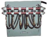
fitted along with hoses, pipes and fittings in a separate Spray Panel Assembly.
The Spray Valves are so arranged in the Spray Panel Assembly that the spray which
comes out of these different Spray Valves covers the entire area to be spray
lubricated. Spray Valves are so constructed that air flow can take place only
when grease flow is established. In case of Spray Panel Assembly fitted on Gear
guard opening for Girth Gear spray lubrication, the Distributors, Air
Manifolds, Pressure Switch etc. are fitted on the outside whereas Spray Valves
are fitted on the inside with hoses and fittings providing arrangement for
adjustment of their position and angle.
The Lubrication System is made ON by starting the
Motor of the Motorized Pumping Station. When grease comes out of the
Distributor and acts on the Spray Valve, air flow is also established and the
spray of air and grease acts on the area being spray lubricated. Grease
lubrication cycle is controlled for a time period by a Timer which, after
preset time, switches off the Motor of the Pumping Station and stops spray
cycle. The next spray cycle is started by a synchronous Timer provided in the
Electrical Control Panel.
CENTRALIZED AUTOMATIC SINGLE
LINE PROGRESSIVE GREASE SPRAY LUBRICATION SYSTEM
I. Schematic Diagramme :
II. Principle of Operation :
Lubricant (grease or oil) is supplied by the
Motorized Pumping Station through the Single Line Progressive Distributor, as
shown in the schematic diagramme. From the outlet of the Distributor, one line
goes to the Spray Valve. Air line is taken through Air Filter / Regulator to
Air Manifolds from which the outlets are connected to the air lines of
different Spray Valves. One Pressure Switch is provided in the air line for
ensuring minimum air pressure. The Distributor, Spray Valves, Air Manifolds,
Pressure Switch etc. are all fitted along with hoses, pipes and fittings in a
separate Spray Panel Assembly. The Spray Valves are so arranged in the Spray
Panel Assembly that the spray which comes out of these different Spray Valves
covers the entire area to be spray lubricated. Spray Valves are so constructed
that air flow can take place only when lubricant flow is established.
The Lubrication System is
made ON by starting the Motor of the Motorized Pumping Station. When
lubricant comes out of the Distributor and acts on the Spray Valve, air flow is
also established and the spray of air and lubricant acts on the area being
spray lubricated. The operation of the Cycle Indicator Switch signals the
completion of one cycle of the Distributor. The duration of spray lubrication
cycle can be adjusted for one cycle or multiple cycles of the Distributor;
alternately, it can be adjusted for a time period by a Timer which, after
preset time, switches off the Motor of the Pumping Station and stops spray
cycle. The next spray cycle is started by another Timer provided in the
Electrical Control Panel.
CENTRALIZED AUTOMATIC SINGLE
LINE PROGRESSIVE OIL SPRAY LUBRICATION SYSTEM
I. Schematic Diagramme :
II. Principle of Operation :
Oil is supplied by the Lubrication Unit
through the Single Line Progressive Distributor, as shown in the schematic
diagramme. From the outlet of the Distributor, one line goes to the Spray
Valve. Air line is taken through Air Filter / Regulator to Air Manifolds from
which the outlets are connected to the air lines of different Spray Valves. One
Pressure Switch is provided in the air line for ensuring minimum air pressure.
The Distributor, Spray Valves, Air Manifolds, Pressure Switch etc. are all
fitted along with hoses, pipes and fittings in a separate Spray Panel Assembly.
The Spray Valves are so arranged in the Spray Panel Assembly that the spray
which comes out of these different Spray Valves covers the entire area to be
spray lubricated. Spray Valves are so constructed that air flow can take place
only when oil flow is established.
The Lubrication System is made ON by
starting the Motor of the Lubrication Unit. When oil comes out of the
Distributor and acts on the Spray Valve, air flow is also established and the
spray of air and oil acts on the area being spray lubricated. The operation of
the Cycle Indicator Switch signals the completion of one cycle of the
Distributor. The duration of spray lubrication cycle can be adjusted for one cycle
or multiple cycles of the Distributor; alternately, it can be adjusted for a
time period by a Timer which, after preset time, switches off the Motor of the
Pumping Station and stops spray cycle. The next spray cycle is started by
another Timer provided in the Electrical Control Panel.
CENTRALIZED AUTOMATIC OIL SPRAY LUBRICATION SYSTEM
I. Schematic Diagramme :
II. Principle of Operation :
Oil is supplied by the Lubrication Unit
through the Oil Distributors in the manner in which the Single Line Oil
Lubrication System works. From the outlet of the Distributor, the line is
connected to the Spray Head. Air line is connected to the Spray Heads through
Solenoid operated ON / OFF Valve and Air Filter / Regulator. The Spray Heads
are so arranged that the spray which comes of the different Spray Heads covers
the entire area to be spray lubricated.
The Lubrication System is made ON by
starting the Motor of the Lubrication Unit and energizing the Solenoid of the
Solenoid Valve. Both oil and air reach the Spray Head, get mixed and come out
in the form of spray. The operation of the Pressure Switch signals the
completion of spray cycle when the Motor is stopped and the Solenoid is
de-energized. Sometimes it is desirable to extend the operation of air flow a
little longer; this can be achieved by providing a suitable time delay. The
next spray lubrication cycle will be started automatically after the desired
interval by a pre-set Timer or Counter.
CENTRALIZED HYDROSTATIC BEARING LUBRICATION SYSTEM
I. Schematic Diagramme :
II. Principle of Operation :
One typical application for the Hydrostatic Bearing Lubrication System is
in Ball Mills. Each Mill is supported on two nos. hydrostatic journal bearings.
The Hydrostatic Bearing Lubrication System commonly called the Hi-lift System
provides pre-jacking of the mill trunions, before start up. The oil is sucked
by a gear pump from the oil sump of the bearing. In the suction line there is a
Ball Valve provided for the purpose of isolation at any time during the
operation of the System. There is also a Y-type Strainer provided in the
suction line. On the delivery side of the pump, a Check Valve is provided for
preventing any return flow. Pressure line is then connected to a Pressure
Switch which gives an electrical command to start the main Mill drive when the pre-set
value of pressure is attained. One Pressure Gauge is provided in the pressure
line by which the pressure can be checked. Before the pressure gauge, one
Needle Valve is fitted which is normally closed; it is opened only when the
pressure is to be checked. One Pressure Relief Valve is fitted on the pressure
line to protect the system pressure going beyond certain maximum value. The
by-pass line from the pressure relief valve is to be connected back to the
sump. The main pressure line is connected to the bottom of the bearing for
pre-jacking.